PoE was invented by PowerDsine back in 1997 and the first power injector ( Midspan) was installed in 1998. Many manufacturespartnered with PowerDsine to make useof this innovation. The Institute ofElectrical and Electronic Engineers (IEEE)was approached to form an internationalstandard to facilitate wide spreaddeployment of the technology.
In June of 2003 the PoE specificationbecame the IEEE 802.3af standarddefining the delivery of safe power overstandard Ethernet cables, Cat5 andCat5E. PowerDsine assisted the industryfurther by providing a service to Ethernetdevice manufacturers to testconformance with the new standard.
To date, over three hundred terminaldevices have been compliance testedby PowerDsine, including most of theleading voice over IP telephones, wirelessaccess points and IP security cameras.Today the University of New Hampshire,being vendor independent, is the officialconformance testing body appointed bythe IEEE.
WHY POWER OVER ETHERNET (POE)?
Whether you consider running IP telephony across your existing data network, or extending the reach of the network with strategically placed wireless access points, or just adding a physical security layer to your premises with IP cameras, the risk of possible failure is increased by having remote devices that need AC power connections. Losing data during a power outage is one thing, but losing data, voice and the company security is something else entirely.
A common goal is to consistently achieve 99.999% availability with 5.3 minutes of downtime per year or less. By connecting a UPS to a PoE source in the communications room, the entire network, including the remotely located resources, is capable of continuous operation during a power outage. Most UPS’s also provide for surge protection which is normally unavailable for remotely connected devices, the disruption created by power surges is more common than that created by power outages.
MANAGE THE RISK
To understand the risk here are some stats reported for North America but are generally applicable to any location. The average number of power outages sufficient to cause IT system malfunction per year at a typical site is 15.
• 90% of the outages are less than five minutes in duration.
• 99% of the outages are less than one hour in duration.
• Total cumulative outage duration is approximately 100 minutes per year.
Based on the theoretical availability and the power protection strategy to achieve five nines or higher, Power over Ethernet sources must be backed up by a UPS. system with a minimum of one hour battery life. This will protect the vast majority of systems.
HOW’S THE ECONOMICS?
For IP telephony, scalability is important; for wireless and security systems, the location is crucial. Understanding one example of the installation costs will highlight the benefits to be gained from PoE in each scenario.
If you are installing a Wireless Access point, you tend to put it in ceiling or high up on a wall out of reach of the general public. This area is usually void of AC outlets, therefore to power the units traditionally an AC contractor is needed to install an outlet. In a private area, average costs are in the region of $200 dependent on country.
In public areas, there is a health and safety issue associated with AC power provisioning, which usually means that the power must be channelled into the wall or supplied through metal conduit. This can increase the costs by a factor of 10. The alternative is to run an Ethernet cable from the Wireless Access point to the Switch or Router. It is very simple, at this location, to connect to a PoE port on the Switch or to use a one port power injector. Either way no AC contactor is needed and worst case scenario you are looking at $50 for the PoE port.
You save money, installation is quicker and easier and there is no disruption while holes are cut into walls. Is there something useful you can do with the money you saved on the installation? Buy a UPS.
UNDERSTAND THE OPTIONS FOR DELIVERING POE
- IEEE802.3af allows for switches to provide power on the Data Pair or the Spare Pair. Most switches select the Data Pair. If you are considering separate Power Injectors called Midspans, the standard states they must use the spare pairs. Therefore you should check your cabling installation to see if you have all pairs or only data pairs. Note that most Midspans cannot be used on a Gigabit connection because there are no Spare Pairs in a Gigabit installation. This is why PowerDsine has the 6000G range to support Gigabit connections.
- An Ethernet cable connected to a PoE source will not carry power if no end device is connected. The IEEE 802.3af standard requires that the source first tests the connected device for compliance to the standard before enabling power. After passing the signature test for compliance, a second test is carried out. This test is to determine the amount of power required at the remote location. This information is recorded by the power source as the Class of PoE.
- Pre-standard Cisco powering method is different from IEEE802.3af in the polarity of the power on the connector and the signature of the end device. So if these devices have to be supported, you will need to know how the cable connection can rectify the polarity of the power and how the power source, Midspan or Switch, can recognize the Cisco signature.
- Pre-Standard capacitive test. There are still legacy devices in the market that were early adopters of PoE and implemented a pre-standard signature based on capacitive signature, which is different obviously from today’s resistive test.
- Devices that do not conform to the PoE specifications can still benefit with the use of a Splitter. The Splitter is mounted next to the remote device and receives the PoE Ethernet cable ac input. It then splits the out put into a standard Ethernet data connection and a separate DC power connection
UNDERSTAND THE POWER REQUIREMENTS OF ATTACHED DEVICES
According to the IEEE 802.3af standard, the amount of power available after 100 meters of Cat5 or cat 5E cable, is up to 12.95 watts. See below the typical power requirements of the most common IP devices. The power consumption of each IP device can be found at the technical specifications of the manufacturer’s data sheets.
Power Levels Available
| Class | Usage | Classification current
[mA] | Power range
[Watt] | Class description |
| 0 | Default | 0–4 | 0.44–12.94 | Classification unimplemented |
| 1 | Optional | 9–12 | 0.44–3.84 | Very Low power |
| 2 | Optional | 17–20 | 3.84–6.49 | Low power |
| 3 | Optional | 26–30 | 6.49–12.95 | Mid power |
| 4 | Valid for 802.3at (Type 2) devices,
not allowed for 802.3af devices | 36–44 | 12.95–25.50 | High power |
IEEE802.3af power is 15.4 watts at the power source and 12.95watts at the Powered Device. However part of the standard’s specification involves testing the class of power, which refers to the specific power requirement of the end device.
As an example, a 7 watt device is Class 2. Manufacturers marketing departments are using this as a tool instead of saying their Switch only supplies 7 watts they say their Switch is a Class 2 PoE conformant device. This is a problem if Wireless AP, Video IP phones or many security cameras should be powered, as these devices require more power than 7W (Class 2).
The standard mechanism when a device requires more power than can be delivered is to disable the power. The solution from the Switch manufacturers is to provide additional external power supplies.
Note: when installing PoE switches with class 2 PoE, you should check the cost and sizing of adding external power supplies before deciding whether to have internal or external PoE capabilities.
The following table from Wikipedia shows the standard PoE parameters and comparison between them:
Standard PoE Parameters and Comparison
| Property | 802.3af (802.3at Type 1) | 802.3at Type 2 |
Power available at PD
| 12.95 W | 25.50 W |
| Maximum power delivered by PSE | 15.40 W | 34.20 W |
| Voltage range (at PSE) | 44.0–57.0 V | 50.0–57.0 V |
| Voltage range (at PD) | 37.0–57.0 V | 42.5–57.0 V |
| Maximum current | 350 mA | 600 mAper mode |
| Maximum cable resistance | 20 Ω (Category 3) | 12.5 Ω (Category 5) |
| Power management | Three power class levels negotiated at initial connection | Four power class levels negotiated at initial connection or 0.1 W steps negotiated continuously |
| Derating of maximum cable ambient operating temperature | None | 5°C with one mode (two pairs) active |
| Supported cabling | Category 3 and Category 5 | Category 5 |
| Supported modes | Mode A (endspan), Mode B (midspan) | Mode A, Mode B |
You do not have to worry about powering non compliant devices ,such as Printers, Fax machines or PC’s because these devices do not carry the IEEE802.3af signature, thus the ports will automatically disable power. However if you are using integrated PoE on a 24 port networking blade and many of the ports are supporting non powered devices, it might be more prudent to use a Midspan and only connect powered ports to the devices that need it. This will lower the overall cost of the installation.
CAUTION REGARDING FULL POWER & FORCED POWER
The question of using managed power or full power has to be considered. Full power is where the power delivered by all ports simultaneously is 15.4 watts. This looks like an attractive option, however the issue to consider is the actual power requirements in an organization. If the installation mainly consists of IP phones with power consumption of 3-5 watts per phone, the overall power consumption will be in the range of 120W. Thus, putting a 24 port PoE injector in the computer room delivering 400 watts is false economy.
All systems installation teams have to calculate the BTU’s and Airflow requirements in the computer room to ensure the air conditioning systems can perform adequately. A better solution is to use power injectors that use the Class of Power information to manage the power delivery to the ports that require higher levels. Power management allows the automation of efficient power distribution from a power injectors with smaller power supplies.
Some PoE injector manufacturers are using the term Forced Power. This is where they leave the power on continuously. This is outside the standard. The IEEE802.3af requires that power is removed within 47 milli- seconds of disconnect. The reason is that an engineer might be swapping cables at a ‘cross connect panel’ and by accident connect a powered port into a PC connection. Today, PC’s cannot be powered using PoE thus 48volts can burn out the Ethernet port at the computer side and it also runs the risk of damaging Switch ports.
CABLE SPECIFICATIONS OFTEN MISSED
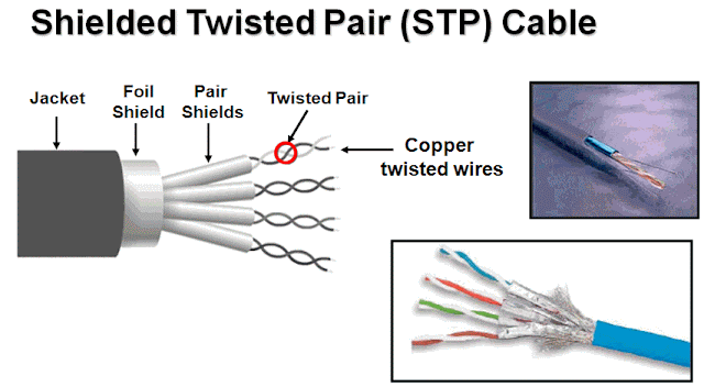
In order to avoid EMI from noise generated by the power source, it is important to conform to the cable specifications of Cat5 and Cat 5E. Among the crucial tests is crosstalk. Devices that do not conform to these specifications will generate excessive errors into the data path. The worst case of cross talk we have measured to date from an uncertified power injector is taking a 10mbps link and dropping it to 1mbps.
There is a defined limit to the current that can be sent down a pair of twisted wires. Currently the ITA specification is 175milliamps on one pair of cables. According to the IEEE802.3af specification for delivering the required power, it is 350 milliamps on two pairs. PoE is running the cable at its maximum allowed capacity. Therefore there is a real need for effective current protection to prevent failing end devices from drawing too much current and causing cable faults.
EVALUATE INTERNAL POWER OR SEPARATE MIDSPAN UNITS
Here are some of the questions to consider when evaluating how to deploy PoE:
1) How old are your Switches and do they have the features such as QOS that fit your requirements? Midspans were designed to be used with any switch and save on the expense and time involved in doing an upgrade to the switch to implement a PoE solution. Midspans can be installed while the network is live with zero down time.
2) Will the proposed Switch have the correct power level to support all devices, or are additional external power supplies needed? What are the costs of these external PSU’s? How much rack space do they take? Can they be redeployed if you change your supplier?
3) What is your history of upgrades? Companies keep their networking switches for 3-10 years. Over the last 5 years how many adaptors did you swap out of the switch for new ones, most probably, with new features? If you are doing 2–3 upgrades, then you will buy power 2–3 times if it is integral to the switch. Compare the purchase cost (over 5 years) between integrated PoE and external Midspans which are designed to be part of the cabling scheme and last for 10 years.
4) How much rack space does the Switch’s external PSU take? Midspans consume rack space. 48-port Midspan from PowerDsine takes 1U.
5) In some cases, integrated PoE will be a better strategy for powering terminals with low power consumption. However, when an external power supply is required for higher power levels, a Midspan solution might be your cost effective choice.
MANAGED OR UNMANAGED POE?
PoE Midspans can be SNMP managed or unmanaged. The areas of relevance to most enterprises are power consumption and the ability to remotely control Power On – Power Off. Management data and control functions need to be secured against unauthorized personnel. A hacker intruding into your network could use the power to disable all peripheral PoE devices.
Wireless Access Points and Security Cameras tend to be installed out of reach of the public. This means they are also not very accessible to engineers. The ability to remotely perform a power on reset could be extremely useful.
IPT requires that all IP phones be powered. SNMP management might be useful as the controlling tool for applications that can power telephones on and off when the relevant staff has passed security into the building and powering the phones off when they leave. It might be interesting for energy conservation to use batch files to enable telephones during work hours and disabling telephones in the evenings, weekends and holidays.
Enterprise users might need to account for power usage by the different departments inside the company. Therefore consideration should be given to the ability of the PoE system to monitor power consumption of the remote devices. Also on power failure, when the UPS kicks in, the management could use a priority scheme to ensure that as the power outage continues, the power is directed to key resources. This management of failed power distribution could enable cost savings in the size of UPS needed for any given scenario. This will extend the life of the UPS support and it is a non linear function. If you halve the load on a UPS, it doesn’t last twice as long, but more like 3-4 times as long. Better value and increased business continuity.
CONCLUSIONS
1) PoE is a must. Savings in power outlet installation costs, the speed of installation and the lack of disruptions to office environments are good justifications for PoE Midspan. The use of a central UPS’s in conjunction with a Midspan to deliver the UPS service to remote locations is a better justification for PoE.
2) Use the Integrated PoE supplied with the switch unless you need higher power than its standard PSU can deliver. Use a Midspan for all additional power and high power requirements.
3) Choose units that conform to the IEEE standard and legacy support where needed.
4) Ensure that they conform to EMI and Xtalk specification and have current protection. The biggest single investment in your network infrastructure is the cable plant so you should protect it.
5) It is recommended to use power management SNMP v3 for secure control, monitoring and management of power distribution. It allows you to control an orderly shut down of connected devices, and optimize the power backup of the UPS in the system.




 UTP Cat6

