Pages

Wednesday, November 23, 2016

Network Cabling

What is Network Cabling?

Cable is the medium through which information usually moves from one network device to another. There are several types of cable which are commonly used with LANs. In some cases, a network will utilize only one type of cable, other networks will use a variety of cable types. The type of cable chosen for a network is related to the network's topology, protocol, and size. Understanding the characteristics of different types of cable and how they relate to other aspects of a network is necessary for the development of a successful network.

The following sections discuss the types of cables used in networks and other related topics.
  • Unshielded Twisted Pair (UTP) Cable
  • Shielded Twisted Pair (STP) Cable
  • Coaxial Cable
  • Fiber Optic Cable

Twisted Pair Cables


Two primary types of twisted pair cable industry standards are defined – Unshielded Twisted Pair (UTP) and Shielded Twisted Pair (STP).

UTP Cable

Unshielded Twisted Pair (UTP) cable is most certainly by far the most popular cable around the world. UTP cable is used not only for networking but also for the traditional telephone (UTP-Cat 1). There are seven different types of UTP categories and, depending on what you want to achieve, you would need the appropriate type of cable. UTP-CAT5e is the most popular UTP cable which came to replace the old coaxial cable that was not able to keep up with the constant growing need for faster and more reliable networks.

UTP Cat6UTP Cat5e

The characteristics of UTP are very good and make it easy to work with, install, expand and troubleshoot and we are going to look at the different wiring schemes available for UTP, how to create a straight through UTP cable, rules for safe operation and a lot of other cool stuff !So let's have a quick look at each of the UTP categories available today along with their specifications: 
STP Cable
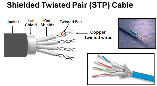
Shielded twisted pair is a special kind of copper telephone wiring used in some business installations. An outer covering or shield is added to the ordinary twisted pair telephone wires; the shield functions as a ground.
Twist Pair Connector

The RJ45 connector works with twisted pair cabling and is the most common type of connector in modern networks. In addition, the RJ45 connector is used on Cisco console cables.


       RJ-45 Connector

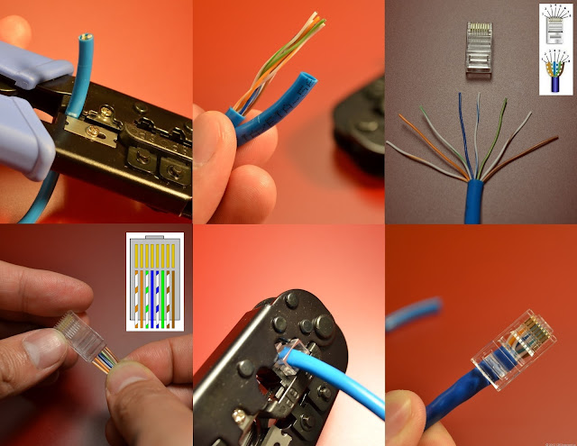
How to crimp network cable with rj45


There are four colors associated with the eight wires within the cable. The colors of the wires determine where they will be terminated in the RJ45 connector. The color code is BlueOrangeGreen, and Brown. For each color, there are two types: "Color + White" & "White + Color". In other words, there are two blue wires – One is mostly blue with white stripes, the other is mostly white with blue stripes. These are referred to as White/Blue & Blue/White.
There are three types of cables you must be familiar with for the CCNA Blueprint: Straight Cable, Crossover Cable, and Rollover Cable. These cable types are determined by where the various colored wires are terminated (installed) within the RJ45 connector.

Straight Cable:
In a straight cable (also called a straight through) cable, the wires are terminated on the same RJ45 pins at both sides of the cable:

Key Topic: A straight cable is used to connect devices that operate at different layers of the OSI Model. For example, a straight cable is used to connect a switch (L2) to a router (L3).
Crossover Cable:
In a crossover cable, four wires are reversed or crossed. Pins 1,2,3,6 on the left are terminated on 3,6,1,2 on the right respectively:

Key Topic: A crossover cable is used to connect two devices that operate on the same layers of the OSI Model. For example, a crossover cable is used to connect a router to another router.

Rollover Cable (AKA Rolled Cable):
A rolled cable is 100% reversed on one side of the cable:

Key Topic: A rolled cable is used to connect to the console port on a Cisco network device (switch / router / etc…).

Coaxial Cables


A type of wire that consists of a center wire surrounded by insulation and then a grounded shield of braided wire. The shield minimizes electrical and radio frequency interference.
Coaxial cabling is the primary type of cabling used by the cable television industry and is also widely used for computer networks, such as Ethernet. Although more expensive than standard telephone wire, it is much less susceptible to interference and can carry much more data.

Coaxial Cable Connectors

The most common type of connector used with coaxial cables is the Bayone-Neill-Concelman (BNC) connector. Different types of adapters are available for BNC connectors, including a T-connector, barrel connector, and terminator. Connectors on the cable are the weakest points in any network. To help avoid problems with your network, always use the BNC connectors that crimp, rather screw, onto the cable.

Fiber Optic Cable

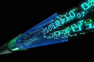
A technology that uses glass (or plastic) threads (fibers) to transmit data. A fiber optic cable consists of a bundle of glass threads, each of which is capable of transmitting messages modulated onto light waves.
Fiber optics has several advantages over traditional metal communications lines:


  • Fiber optic cables have a much greater bandwidth than metal cables. This means that they can carry more data.
  • Fiber optic cables are less susceptible than metal cables to interference.
  • Fiber optic cables are much thinner and lighter than metal wires.
  • Data can be transmitted digitally (the natural form for computer data) rather than analogically.

  •                                Fiber Optic 

  • Fiber Optic have to mode: Single Mode and Multi-mode


    Fiber Optic Connectors


    Tuesday, November 22, 2016

    Advanced Subnet Calculator

    There is a lot more to managing your IP network than simple subnetting

    Network discovery

    Before you can manage subnets, you need to know how your network is being used. Do you know?

    Network subnetting

    Whether you are creating or combining subnets, one mistake can cause problems. Do you have the tools to make error-free changes?

    IP address tracking

    Once the network is organized, do you have the tools to track which IP addresses are in use or available?

    Download click link bellow : SolarWinds-Subnet-Calculator

    Sunday, November 20, 2016

    How to use Rufus to create a bootable USB drive to install any OS (Window and Linux)


    1. Rufus requires an account with admin access in order to make the necessary changes to hardware. After authenticating, insert the USB flash drive and launch Rufus. It will detect the drive almost immediately. Since Rufus can handle various partition schemes and file structures, ensure that the correct settings are set that match the UFD you're going to build.
    2. Click the optical drive button next to the Create a bootable disk using checkbox, and you'll be prompted to search for the ISO image to use.
    3. When using ISO images, Rufus will automatically modify the settings to best match it. Once everything is set correctly, click the Start button to begin the process. You'll be prompted with a warning that all data on the UFD will be destroyed. Click OK to proceed with the creation process.
    4. Depending on the ISO image size, the process may take several minutes to complete. For the log readout of each step in the process, click the Log button to open a side window and save the output details.
    5. Wait until finish and you will show in flash like this:


    Please download rufus by click this link: rufus-2.9.exe

    POWER OVER ETHERNET - UNDERSTANDING POE TECHNOLOGY, POE OPTIONS & POWER REQUIREMENTS

     PoE was invented by PowerDsine back in 1997 and the first power injector ( Midspan) was installed in 1998. Many manufacturespartnered with PowerDsine to make useof this innovation. The Institute ofElectrical and Electronic Engineers (IEEE)was approached to form an internationalstandard to facilitate wide spreaddeployment of the technology.
    In June of 2003 the PoE specificationbecame the IEEE 802.3af standarddefining the delivery of safe power overstandard Ethernet cables, Cat5 andCat5E. PowerDsine assisted the industryfurther by providing a service to Ethernetdevice manufacturers to testconformance with the new standard.
    To date, over three hundred terminaldevices have been compliance testedby PowerDsine, including most of theleading voice over IP telephones, wirelessaccess points and IP security cameras.Today the University of New Hampshire,being vendor independent, is the officialconformance testing body appointed bythe IEEE.

    WHY POWER OVER ETHERNET (POE)?

    Whether you consider running IP telephony across your existing data network, or extending the reach of the network with strategically placed wireless access points, or just adding a physical security layer to your premises with IP cameras, the risk of possible failure is increased by having remote devices that need AC power connections. Losing data during a power outage is one thing, but losing data, voice and the company security is something else entirely.
    A common goal is to consistently achieve 99.999% availability with 5.3 minutes of downtime per year or less. By connecting a UPS to a PoE source in the communications room, the entire network, including the remotely located resources, is capable of continuous operation during a power outage. Most UPS’s also provide for surge protection which is normally unavailable for remotely connected devices, the disruption created by power surges is more common than that created by power outages.


    MANAGE THE RISK

    To understand the risk here are some stats reported for North America but are generally applicable to any location. The average number of power outages sufficient to cause IT system malfunction per year at a typical site is 15.
    •   90% of the outages are less than five minutes in duration.
    •   99% of the outages are less than one hour in duration.
    •   Total cumulative outage duration is approximately 100 minutes per year.
    Based on the theoretical availability and the power protection strategy to achieve five nines or higher, Power over Ethernet sources must be backed up by a UPS. system with a minimum of one hour battery life. This will protect the vast majority of systems. 

    HOW’S THE ECONOMICS?

    For IP telephony, scalability is important; for wireless and security systems, the location is crucial. Understanding one example of the installation costs will highlight the benefits to be gained from PoE in each scenario.
    If you are installing a Wireless Access point, you tend to put it in ceiling or high up on a wall out of reach of the general public. This area is usually void of AC outlets, therefore to power the units traditionally an AC contractor is needed to install an outlet. In a private area, average costs are in the region of $200 dependent on country.
    In public areas, there is a health and safety issue associated with AC power provisioning, which usually means that the power must be channelled into the wall or supplied through metal conduit. This can increase the costs by a factor of 10. The alternative is to run an Ethernet cable from the Wireless Access point to the Switch or Router. It is very simple, at this location, to connect to a PoE port on the Switch or to use a one port power injector. Either way no AC contactor is needed and worst case scenario you are looking at $50 for the PoE port.
    You save money, installation is quicker and easier and there is no disruption while holes are cut into walls. Is there something useful you can do with the money you saved on the installation? Buy a UPS.

    UNDERSTAND THE OPTIONS FOR DELIVERING POE

    • IEEE802.3af allows for switches to provide power on the Data Pair or the Spare Pair. Most switches select the Data Pair. If you are considering separate Power Injectors called Midspans, the standard states they must use the spare pairs. Therefore you should check your cabling installation to see if you have all pairs or only data pairs. Note that most Midspans cannot be used on a Gigabit connection because there are no Spare Pairs in a Gigabit installation. This is why PowerDsine has the 6000G range to support Gigabit connections.

    • An Ethernet cable connected to a PoE source will not carry power if no end device is connected. The IEEE 802.3af standard requires that the source first tests the connected device for compliance to the standard before enabling power. After passing the signature test for compliance, a second test is carried out. This test is to determine the amount of power required at the remote location. This information is recorded by the power source as the Class of PoE.

    • Pre-standard Cisco powering method is different from IEEE802.3af in the polarity of the power on the connector and the signature of the end device.  So if these devices have to be supported, you will need to know how the cable connection can rectify the polarity of the power and how the power source, Midspan or Switch, can recognize the Cisco signature.

    • Pre-Standard capacitive test. There are still legacy devices in the market that were early adopters of PoE and implemented a pre-standard signature based on capacitive signature, which is different obviously from today’s resistive test.

    • Devices that do not conform to the PoE specifications can still benefit with the use of a Splitter. The Splitter is mounted next to the remote device and receives the PoE Ethernet cable ac input. It then splits the out put into a standard Ethernet data connection and a separate DC power connection
     
    UNDERSTAND THE POWER REQUIREMENTS OF ATTACHED DEVICES

     
    According to the IEEE 802.3af standard,  the amount of power available after 100 meters of Cat5 or cat 5E cable, is up to 12.95 watts. See below the typical power requirements of the most common IP devices. The power consumption of each IP device can be found at the technical specifications of the manufacturer’s data sheets.


    Power Levels Available
    ClassUsageClassification current
    [mA]
    Power range
    [Watt]
    Class description
    0Default0–40.44–12.94Classification unimplemented
    1Optional9–120.44–3.84Very Low power
    2Optional17–203.84–6.49Low power
    3Optional26–306.49–12.95Mid power
    4Valid for 802.3at (Type 2) devices,
    not allowed for 802.3af devices
    36–4412.95–25.50High power
    IEEE802.3af power is 15.4 watts at the power source and 12.95watts at the Powered Device. However part of the standard’s specification involves testing the class of power, which refers to the specific power requirement of the end device.
    As an example, a 7 watt device is Class 2. Manufacturers marketing departments are using this as a tool instead of saying their Switch only supplies 7 watts they say their Switch is a Class 2 PoE conformant device. This is a problem if Wireless AP, Video IP phones or many security cameras should be powered, as these devices require more power than 7W (Class 2).
    The standard mechanism when a device requires more power than can be delivered is to disable the power. The solution from the Switch manufacturers is to provide additional external power supplies.
    Note: when installing PoE switches with class 2 PoE, you should check the cost and sizing of adding external power supplies before deciding whether to have internal or external PoE capabilities.
    The following table from Wikipedia shows the standard PoE parameters and comparison between them:

    Standard PoE Parameters and Comparison
    Property802.3af (802.3at Type 1)802.3at Type 2
    Power available at PD
    12.95 W25.50 W
    Maximum power delivered by PSE15.40 W34.20 W
    Voltage range (at PSE)44.0–57.0 V50.0–57.0 V
    Voltage range (at PD)37.0–57.0 V42.5–57.0 V
    Maximum current350 mA600 mAper mode
    Maximum cable resistance20 Ω (Category 3)12.5 Ω (Category 5)
    Power managementThree power class levels negotiated at initial connectionFour power class levels negotiated at initial connection or 0.1 W steps negotiated continuously
    Derating of maximum cable ambient operating temperatureNone5°C with one mode (two pairs) active
    Supported cablingCategory 3 and Category 5Category 5
    Supported modesMode A (endspan), Mode B (midspan)Mode A, Mode B


    You do not have to worry about powering non compliant devices ,such as Printers, Fax machines or PC’s because these devices do not carry the IEEE802.3af signature, thus the ports will automatically disable power.  However if you are using integrated PoE on a 24 port networking blade and many of the ports are supporting non powered devices, it might be more prudent to use a Midspan and only connect powered ports to the devices that need it. This will lower the overall cost of the installation.

     CAUTION REGARDING FULL POWER & FORCED POWER

    The question of using managed power or full power has to be considered. Full power is where the power delivered by all ports simultaneously is 15.4 watts. This looks like an attractive option, however the issue to consider is the actual power requirements in an organization. If the installation mainly consists of IP phones with power consumption of  3-5 watts per phone, the overall power consumption will be in the range of 120W. Thus, putting a 24 port PoE injector in the computer room delivering 400 watts is false economy.
    All systems installation teams have to calculate the BTU’s and Airflow requirements in the computer room to ensure the air conditioning systems can perform adequately. A better solution is to use power injectors that use the Class of Power information to manage the power delivery to the ports that require higher levels. Power management allows the automation of efficient power distribution from a power injectors with smaller power supplies.
    Some PoE injector manufacturers are using the term Forced Power. This is where they leave the power on continuously. This is outside the standard. The IEEE802.3af requires that power is removed within 47 milli- seconds of disconnect. The reason is that an engineer might be swapping cables at a ‘cross connect panel’ and by accident connect a powered port into a PC connection. Today, PC’s cannot be powered using PoE thus 48volts can burn out the Ethernet port at the computer side and it also runs the risk of damaging Switch ports.

     CABLE SPECIFICATIONS OFTEN MISSED

    In order to avoid EMI from noise generated by the power source, it is important to conform to the cable specifications of Cat5 and Cat 5E. Among the crucial tests is crosstalk. Devices that do not conform to these specifications will generate excessive errors into the data path. The worst case of cross talk we have measured to date from an uncertified power injector is taking a 10mbps link and dropping it to 1mbps.
    There is a defined limit to the current that can be sent down a pair of twisted wires. Currently the ITA specification is 175milliamps on one pair of cables. According to the IEEE802.3af specification for delivering the required power, it is 350 milliamps on two pairs. PoE is running the cable at its maximum allowed capacity. Therefore there is a real need for effective current protection to prevent failing end devices from drawing too much current and causing cable faults.
    EVALUATE INTERNAL POWER OR SEPARATE MIDSPAN UNITS
    Here are some of the questions to consider when evaluating how to deploy PoE:
    1) How old are your Switches and do they have the features such as QOS that fit your requirements? Midspans were designed to be used with any switch and save on the expense and time involved in doing an upgrade to the switch to implement a PoE solution. Midspans can be installed while the network is live with zero down time.
    2) Will the proposed Switch have the correct power level to support all devices, or are additional external power supplies needed? What are the costs of these external PSU’s? How much rack space do they take? Can they be redeployed if you change your supplier?
    3) What is your history of upgrades? Companies keep their networking switches for 3-10 years.  Over the last 5 years how many adaptors did you swap out of the switch for new ones, most probably, with new features? If you are doing 2–3 upgrades, then you will buy power 2–3 times if it is integral to the switch. Compare the purchase cost (over 5 years) between integrated PoE and external Midspans which are designed to be part of the cabling scheme and last for 10 years.
    4) How much rack space does the Switch’s external PSU take? Midspans consume rack space. 48-port Midspan from PowerDsine takes 1U.
    5) In some cases, integrated PoE will be a better strategy for powering terminals with low power consumption. However, when an external power supply is required for higher power levels, a Midspan solution might be your cost effective choice.

     MANAGED OR UNMANAGED POE?

    PoE Midspans can be SNMP managed or unmanaged. The areas of relevance to most enterprises are power consumption and the ability to remotely control Power On – Power Off. Management data and control functions need to be secured against unauthorized personnel. A hacker intruding into your network could use the power to disable all peripheral PoE devices.
    Wireless Access Points and Security Cameras tend to be installed out of reach of the public. This means they are also not very accessible to engineers.  The ability to remotely perform a power on reset could be extremely useful.
    IPT requires that all IP phones be powered. SNMP management might be useful as the controlling tool for applications that can power telephones on and off when the relevant staff has passed security into the building and powering the phones off when they leave. It might be interesting for energy conservation to use batch files to enable telephones during work hours and disabling telephones in the evenings, weekends and holidays.
    Enterprise users might need to account for power usage by the different departments inside the company. Therefore consideration should be given to the ability of the PoE system to monitor power consumption of the remote devices.  Also on power failure, when the UPS kicks in, the management could use a priority scheme to ensure that as the power outage continues, the power is directed to key resources. This management of failed power distribution could enable cost savings in the size of UPS needed for any given scenario. This will extend the life of the UPS support and it is a non linear function. If you halve the load on a UPS, it doesn’t last twice as long, but more like 3-4 times as long. Better value and increased business continuity.
    CONCLUSIONS
    1) PoE is a must. Savings in power outlet installation costs, the speed of installation and the lack of disruptions to office environments are good justifications  for PoE Midspan. The use of a central UPS’s in conjunction with a Midspan to deliver the UPS service to remote locations is a better justification for PoE.
    2) Use the Integrated PoE supplied with the switch unless you need higher power than its standard PSU can deliver. Use a Midspan for all additional power and high power requirements.
    3) Choose units that conform to the IEEE standard and legacy support where needed.
    4) Ensure that they conform to EMI and Xtalk specification and have current protection. The biggest single investment in your network infrastructure is the cable plant so you should protect it.
    5) It is recommended to use power management SNMP v3 for secure control, monitoring and management of power distribution. It allows you to control an orderly shut down of connected devices, and optimize the power backup of the UPS in the system.

    SWITCHES & BRIDGES

    INTRODUCTION

    By now you can see the limitations of a simple hub and when you also read about Ethernet, you start to understand that there are even more limitations. The companies who manufacter hubs saw the big picture quickly and came out with something more efficient, bridges, and then the switches came along! Bridges are analysed later on in this section.

    SWITCHING TECHNOLOGY

    As we mentioned earlier, hubs work at the first layer of the OSI model and simply receive and transmit information without examining any of it.
    Switches (Layer-2 Switching) are a lot smarter than hubs and operate on the second layer of the OSI model. What this means is that a switch won't simply receive data and transmit it throughout every port, but it will read the data and find out the packet's destination by checking the MAC address. The destination MAC address is located always at the beginning of the packet so once the switch reads it, it is forwarded to the appropriate port so no other node or computer connected to the switch will see the packet.
    Switches use Application Specific Integrated Circuits (ASIC's) to build and maintain filter tables.
    Layer-2 switches are alot faster than routers cause they dont look at the Network Layer (thats Layer-3) header or if you like, information. Instead all they look at is the frame's hardware address (MAC address) to determine where the frame needs to be forwarded or if it needs to be dropped. If we had to point a few features of switches we would say:
    • They provide hardware based bridging (MAC addresses)
    • They work at wire speed, therefor have low latency
    • They come in 3 different types: Store & Forward, Cut-Through and Fragment Free (Analysed later)
    Below is a picture of two typical switches. Notice how they looks similair to a hubs, but they aren't. It's just that the difference is on the inside!
                          Unmanage Switches
    Cisco SMB Switch

    THE THREE STAGES

    All switches regardless of the brand and various enhancements they carry, have something in common, it's the three stages (sometimes 2 stages) they go through when powered up and during operation. These are as follows:
    • Address Learning
    • Forward/Filter decisions
    • Loop Avoidance (Optional)
    Let's have a look at them to get a better understanding!
     ADDRESS LEARNING
    When a switch is powered on, the MAC filtering table is empty. When a device transmits and an interface receives a frame, the switch places the source address in the MAC filtering table remembering the interface the device on which it is located. The switch has no choice but to flood the network with this frame because it has no idea where the destination device is located.

    If a device answers and sends a frame back, then the switch will take the source address from that frame and place the MAC address in the database, associating this address with the interface that received the frame.
    Since the switch has two MAC addresses in the filtering table, the devices can make a point-to-point connection and the frames will only be forwarded between the two devices. This makes layer-2 switches better than hubs. As we explained early on this page, in a hub network all frames are forwarded out to all ports every time. Most desktop switches these days can hold upto 8000 MAC addresses in their table, and once the table is filled, then starting with the very first MAC entry, the switch will start overwritting the entries. Even tho the number of entries might sound big .. it only takes a minute or two to fill it up, and if a workstation dosen't talk on the network for that amount of time, then chances are that its MAC address has been removed from the table and the switch will forward to all ports the packet which has as a destination this particular workstation.
    And after the first frame has been successfully received by Node 2, Node 2 sends a reply to Node 1, check out what happens:
    Notice how the frame is not transmitted to every node on the switch. The switch by now has already learned that Node 1 is on the first port, so it send it straight there without delay. From now on, any communication between the two will be a point-to-point connection :

    FORWARD/FILTER DECISION

    When a frame arrives at the switch, the first step is to check the destination hardware address, which is compaired to the forward/filter MAC database. If the destination hardware address is known, then it will transmit it out the correct port, but if the destination hardware address is not known, then it will broadcast the frame out of all ports, except the one which it received it from. If a device (computer) answers to the broadcast, then the MAC address of that device is added to the MAC database of the switch.

    LOOP AVOIDANCE (OPTIONAL)

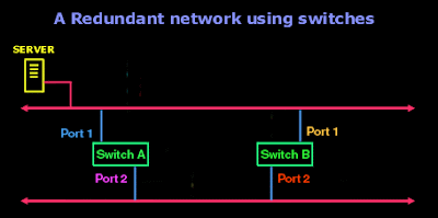
    It's always a good idea to have a redundant link between your switches, in case one decides to go for a holiday. When you setup redundant switches in your network to stop failures, you can create problems. Have a look at the picture below and I'll explain:
    The above picture shows an example of two switches which have been placed in the network to provide redundancy in case one fails. Both switches have their first port connected to the upper section of the network, while their port 2 is connected to the lower section of the same network. This way, if Switch A fails, then Switch B takes over, or vice versa.
    Things will work fine until a broadcast come along and causes alot of trouble. For the simplicity of this example, I am not going to show any workstations, but only the server which is going to send a broadcast over the network, and keep in mind that this is what happens in real life if your switch does not support Spanning-Tree Protocol (STP), this is why I stuck the "Optional" near the "Loop Avoidance" at the start of this section:
    It might look a bit messy and crazy at a first glance but let me explain what is going on here.
    The Server for one reason or another decides to do a broadcast. This First Round (yellow arrow) broadcast is sent down to the network cable and firstly reaches Port 1 on Switch A. As a result, since Switch A has Port 2 connected to the other side of the lan, it sends the broadcast out to the lower section of the network, this then is sent down the wire and reaches Port 2 on Switch B which will send it out Port 1 and back onto the upper part of the network. At this point, as the arrows indicate (orange colour) the Second Round of this broadcast starts. So again... the broadcast reaches Port 1 of Switch A and goes out Port 2 back down to the lower section of the network and back up via Port 2 of Switch B. After it comes out of Port 1 of Switch B, we get the Third Round (Cyan arrow), and then the Fourth Round (pink arrows) , Fifth Round (blue arrows) and keeps on going without stopping.....! This is what we call a Broadcast Storm.
    A Broadcast Storm will repeat constantly, chewing up the valueble bandwidth on the network. This is a major problem, so they had to solve it one way or another, and they did... with the Spanning-Tree Protocol or STP in short. What STP does, is to find the redundant links, which this case would be Port 2 of Switch B and shut it down, thus eliminating the posibility of looping to occur.

    LAN SWITCH TYPES

    At the begining of this page we said that the switches are fast, therefor have low latency. This latency does vary and depends on what type of switching mode the switch is operating at. You might recall seeing these three switching modes at the beginning: Store & ForwardCut-ThroughandFragment Free.
    The picture below shows how far the different switching modes check the frame:
    So what does this all mean ? Switching modes ? I Don't understand !
    Let's Explain!
    The fact is that switches can operate in one of the three modes. Some advance switches will allow you to actually pick the mode you would like it to operate in, while others don't give you any choice. Let's have a quick look at each mode:
     STORE & FORWARD MODE
    This is one of the most popular swtiching methods. In this mode, when the switch receives a frame from one of it's ports, it will store it in memory, check it for errors and corruption, and if it passes the test, it will forward the frame out the designated port, otherwise, if it discovers that the frame has errors or is corrupt, it will discard it. This method is the safest, but also has the highest latency.
     CUT-THROUGH (REAL TIME)
    Cut-Through switching is the second most popular method. In this mode,the switch reads the frame until it learns the destination MAC address of the frame it's receiving. Once it learns it, it will forward the frame straight out the designated port without delay. This is why we say it's -Real Time-, there is no delay or error checking done to the frame.
     FRAGMENT FREE
    The Fragment free switching method is mainly used to check for frames which have been subject to a collision. The frame's first 64 bytes are only checked before forwarding the frame out the designated port. Reason for this is because almost all collisions will happen within the first 64 bytes of a frame. If there is a corruption in the first 64 bytes, it's most likely that that frame was a victim of a collision.
    Just keep one important detail in mind: When you go out to buy a switch, make sure you check the amount of memory it has. Alot of the cheap switches which support the Store & Forward mode have very small amounts of memory buffer (256KB- 512KB) per port. The result of this is that you get a major decrease in performance when you have more than 2 computers communicating via that switch cause there isn't enough memory to store all incoming packets (this also depends on th swtiching type your switch supports), and you eventually get packets being discarded.
    The table below is a guide on what amounts of memory you should be looking at for switches of different configuration :

    NETWORK BRIDGES

    Bridges are really just like switches, but there are a few differences which we will mention, but not expand upon. These are the following:
    • Bridges are software based, while switches are hardware based because they use an ASICs chip to help them make filtering decisions.
    • Bridges can only have one spanning-tree instance per bridge, while switches can have many.
    • Bridges can only have upto 16 ports, while a switch can have hundreds !
    That's pretty much as far as we will go with the bridges since they are pretty much old technology and you probably won't see many around.